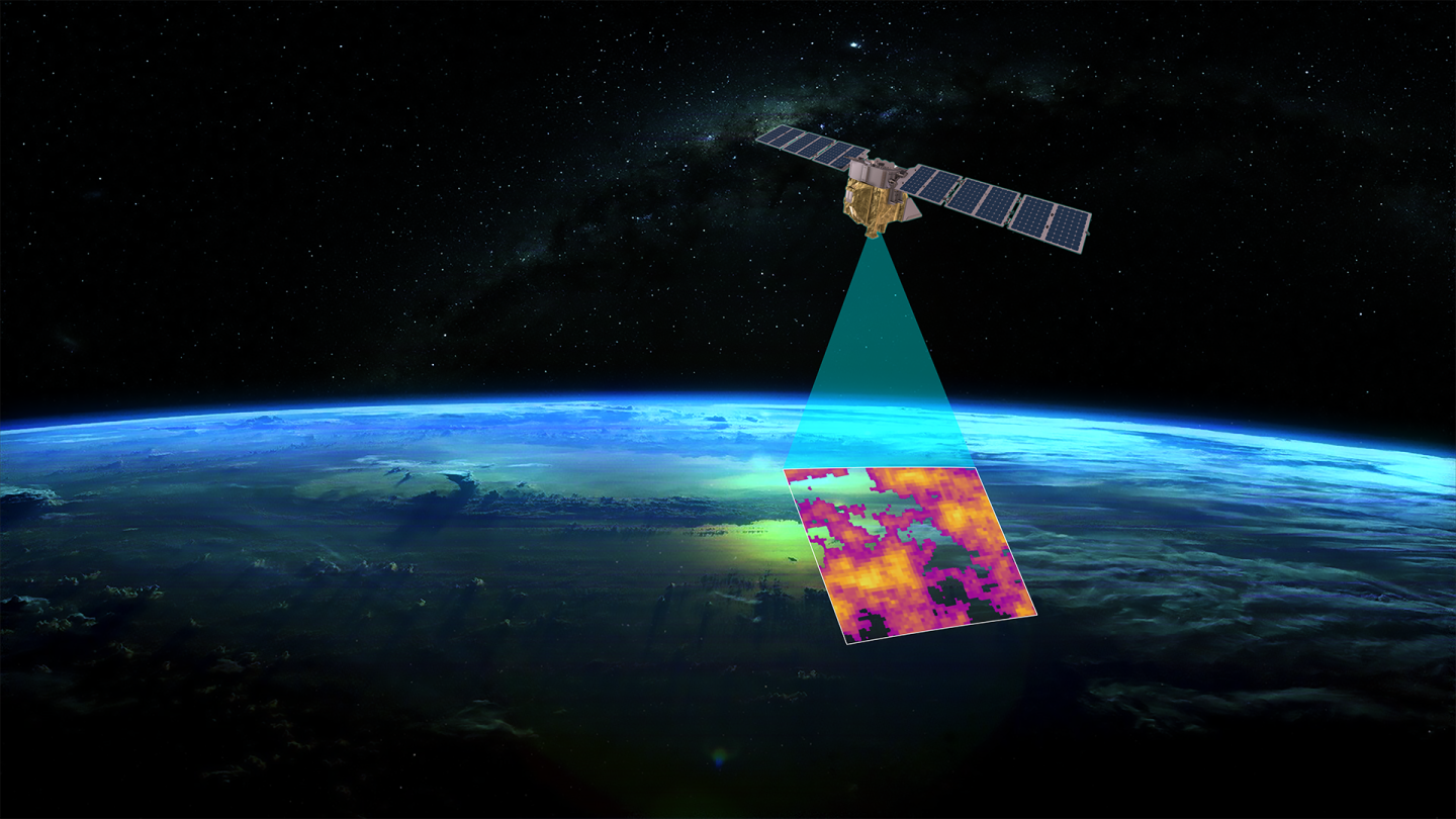
MethaneSat, a project spearheaded by the Environmental Defence Fund, is revolutionising monitoring of flare gas and general methane leakage by providing high-resolution satellite data. By capturing accurate and frequent data, MethaneSat can identify and quantify point emissions sources, or combine measurements in a locality, or even a whole region, enabling anyone oversight and hitherto unprecedented detail on which sites are emitting methane.
Of course, the oil and gas industry is under ever-intensifying environmental scrutiny, with flaring, in particular, coming under critical investigation. As the world grapples with the urgent need to mitigate climate change, the focus on reducing greenhouse gas emissions has sharpened. Flaring not only wastes a valuable energy resource, it contributes significantly to atmospheric pollution, making it a high-priority target for environmental groups and regulators.

Ensuring the transparency, accuracy and reliability of measurement and reporting in this sector has become paramount. Not just for regulatory compliance, but for environmental accountability, and the implementation of effective reduction strategies.
The industry faces growing pressure from governments, environmental organisations, and the public to adopt more sustainable practices.. As the push for cleaner energy intensifies, the role of precise data in driving meaningful environmental action cannot be overstated.
Facing Tightening EPA Regulations
The EPA are planning several significant rule changes to address gas flaring and methane emissions in the oil and gas sector. In August 2023, the EPA announced a rule that aims to dramatically reduce methane emissions, and are backing this up with fiscal muscle. Operators not measuring or meeting the the Net Heating Value requirements of their Flare Gas are no longer able to claim the 98% combustion efficiency which has been a long-time industry assumption. The situation gets worse for operators not continuously measuring their flare gas, or that don’t have continuous monitoring of pilot lights. (40 CFR 98 subpart W).
This is on top of new regulations introducing a phased ban on routine flaring of natural gas from new oil wells, allowing it only in emergencies. Existing wells emitting above 40 tons per year are restricted from flaring unless there are no feasible alternatives or sales lines.
The EPA has also updated the Greenhouse Gas Reporting Program to enhance transparency and accuracy in emissions data. This involves incorporating advanced technologies such as satellite data to identify super-emitters and requiring direct monitoring of key emission sources (US EPA). New criteria and standards for equipment and leak detection have been set, including zero-emissions standards for pneumatic pumps and controllers and specific protocols for addressing methane leaks.
These tightening regulatory changes are all part of the broader US Methane Emissions Reduction Plan, supported by the Inflation Reduction Act, which aims to cut methane emissions across various sectors, including oil and gas. In short, accurate measurement has never been so important.
The Flare Gas Measurement Technology
Ultrasonic flare measurement has become the standard for monitoring flare gas. Its ability to address variable gas velocity, composition, density, and sound of speed challenges is unparalleled. Whereas other methods like pressure meters, turbine meters, Coriolis mass flow meters, thermal mass flow meters, and optical flow meters, often struggle with accuracy under dynamic conditions, ultrasonic sensors offer a robust and reliable solution.
Ultrasonic sensors accurately measure the transit time of sound waves through the gas, with an accuracy measured in nanoseconds. Their adaptability allows them to adjust to changes in gas properties continuously without recalibration, ensuring consistent accuracy even during rapid fluctuations.
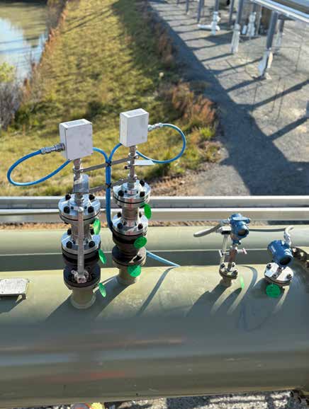
Furthermore, with the optimum configuration, ultrasonic flare measurement systems are non-intrusive, minimising maintenance needs, operational disruptions and ensuring stability in blow-down scenarios. Their durability and reliability make them suitable for harsh industrial environments where other methods may fall short. As a result, ultrasonic technology is now the preferred choice for flare gas monitoring, ensuring both efficiency and safety in operations.
The Challenges Associated with Using Ultrasound
Ironically, carbon dioxide (CO2), a critical gas to measure for assessing the environmental impact of gas flaring, is also one of the hardest to measure accurately when even relatively low concentrations of the gas are present in flare lines.
Measurement of CO2 is difficult due to the gas’s high attenuation of ultrasonic frequencies.
The molecular structure of CO2, comprising one carbon atom and two oxygen atoms, has distinct vibrational modes that actually absorb ultrasonic energy. When ultrasonic waves pass through CO2, the energy can resonate with the CO2 molecules’ natural frequencies, causing significant energy absorption and conversion into internal vibrations.
CO2‘s physical properties, such as density and compressibility, further exacerbate the problem of attenuation. These characteristics combine to mean regular ultrasonic meters are all but useless where concentrations of 30% or more are present.
In practice, the high attenuation of CO2 complicates ultrasonic inspection, imaging, and measurement techniques. Addressing this issue requires careful selection of ultrasonic frequencies and potentially employing alternative methods or compensatory techniques to mitigate attenuation effects, ensuring accurate results.
Solving the problem of measuring CO2 in flare gas opens up the possibility of using the most accurate ultrasonic sensors in a much wider range of applications than is presently the case. When combined with gas composition data, this therefore allows for better optimization of flare efficiency, reducing waste and improving energy use.
A Solution to the Global Flare Gas Measurement Market
In late 2022, FlarePhase transducers from Fluenta were launched aimed at offering a broader operating temperature range compared to other options, but their resistance to extreme temperature fluctuations is just one aspect. There is an unsatisfied demand for ultrasonic measurement systems that can handle processes with much higher CO2 content, and FlarePhase technology offers a significant advantage in this regard.

In many regions, ultrasonic measurement of flare gas is mandated for its accuracy, regardless of gas composition. However, the presence of high CO2 levels prevents this during certain process scenarios, and so a combination of measurement technologies tends to be used – with all the incumbent costs, drawbacks and maintenance that comes with that.
FlarePhase, a new generation of sensor from Fluenta, operates differently from most ultrasonic transducers. All ultrasonic systems require transmitter and receiver resonant frequencies to be matched in order to achieve the optimum signal strength. Even slight deviations, which result from in-process temperature swings, can cause the signal strength to fall off rapidly.
In FlarePhase transducers, Fluenta continuously measure the transducers’ resonant frequencies and adjust the drive signals in real time so they are always perfectly matched. This has obvious benefits where temperature swings are commonplace but can also offer transformative performance when dealing with high levels of CO2. Other techniques such as signal amplification, can help a bit, but are marginal when compared with resonance tracking.
A very thorough approach to signal processing enhances the received signal, allowing the time-of-flight measurements to be accurate to nanoseconds, even where the noise-floor would ordinarily bury such tiny signals. This unique approach allows FlarePhase transducers to maintain the highest accuracy even when faced with high CO2-induced signal attenuation.
A Well-Tested Solution
Extensive reference measurements have been conducted at Fluenta’s test facilities in both the Cambridge, UK and a specially constructed facility at IPT in Brazil.
In Cambridge, it was found that in a 12-inch pipe with velocities of around 25ms-1, we could measure with over 94% CO2 (the maximum concentration possible in our in-house flow loop). Further tests at IPT Brazil confirmed stable and accurate flow measurements even with a mixture of 90% CO2 through the 12” spool and 70% CO2 through the 16” spool, in velocities of up to 75ms-1. Enough to confidently lead the pack in high CO2 measurement.
For the tests, IPT Brazil constructed a 20-inch flow loop facility specifically tailored to Fluenta’s needs. This CO2 loop featured pipes with 12 to 20 inches diameters, supporting maximum flows of 16,000 m³/h and varying linear flows depending on the pipe size. The loop included a heat exchanger to stabilise gas temperature, and a real-time analyser and a gas chromatograph verified the CO2/air mixtures up to 99% CO2.
This article appeared in the Brazilian magazine Química e Derivados.


